|
|
|
Porsche, and the Porsche crest are registered trademarks of Dr. Ing. h.c. F. Porsche AG.
This site is not affiliated with Porsche in any way. Its only purpose is to provide an online forum for car enthusiasts. All other trademarks are property of their respective owners. |
|
|

  |

| ThePaintedMan |
 Dec 17 2013, 12:19 PM Dec 17 2013, 12:19 PM
Post
#21
|
|
Advanced Member  Group: Members Posts: 3,886 Joined: 6-September 11 From: St. Petersburg, FL Member No.: 13,527 Region Association: South East States |
Next, move on to installing the accelerator pump jets. If you have a jet gauge (and I highly recommend you do), gently push it into the nozzle to remove any final remnants of gum or other material that may be stuck here. If you do not, and end up having a plugged pump jet after installation, you'll be forced to pull the top of the carburetor off again to clean them. As tempting as it might be, do not use a staple or other object, as the jet orifices are very small and you risk reaming them out to some unknown size.
Place one of the copper/brass sealing rings on the pump hold down screw, then the jet, then one more sealing ring. They should sandwich the jet from top and bottom. Tighten the screw down firmly but without excessive force using a wide-blade flathead screwdriver. Attached thumbnail(s) 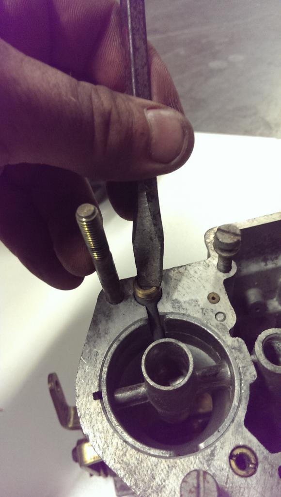
|
   |

 
|
| ThePaintedMan |
Dec 17 2013, 12:28 PM
Post
#22
|
|
Advanced Member Group: Members Posts: 3,886 Joined: 6-September 11 From: St. Petersburg, FL Member No.: 13,527 Region Association: South East States |
Next, begin installing the remaining hardware on the outside of the carb body. This includes the air bypass screws, idle mixture screws, vacuum port plugs (if equipped), and the idle speed screws. I recommend using a very small amount of anti-seize on them as it will make it much easier to make adjustments by hand when tuning later on. You also may wish to clean up any gum deposits on the faces of the needles with fine grit sandpaper. As mentioned by rhodyguy, don't forget the small o-rings that go under the caps for the idle mixture screws, and make darn sure you don't lose them! Also, be sure to install them on your idle jet holders as well.
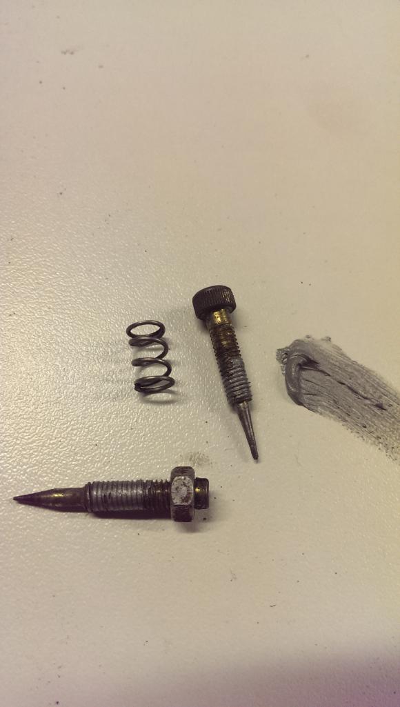 Here is how the final setup should look. 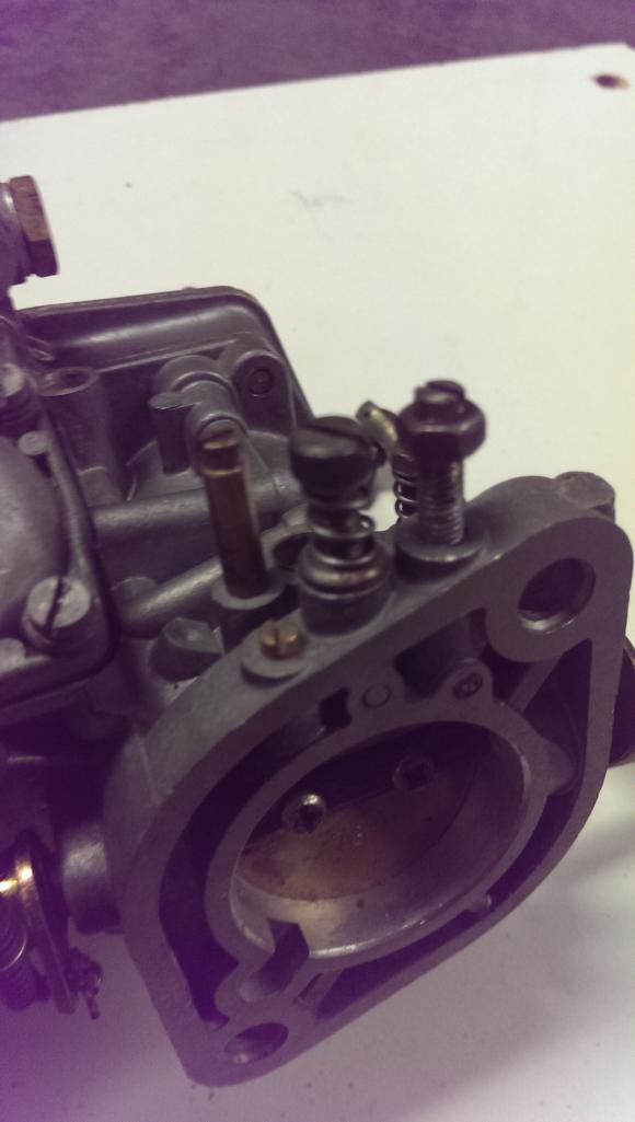 Also, note the difference in size between the idle mixture screw springs and the idle return springs. The return spring is a little beefier. Attached thumbnail(s) 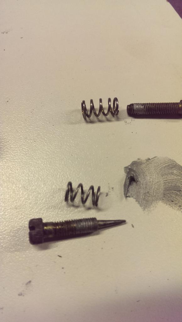
|
|
|
|
| ThePaintedMan |
Dec 17 2013, 12:37 PM
Post
#23
|
|
Advanced Member Group: Members Posts: 3,886 Joined: 6-September 11 From: St. Petersburg, FL Member No.: 13,527 Region Association: South East States |
Now move on to the accelerator pump cover.
Note that there are two style of pump covers and associated diaphragms. If your carbs have and adjustable pump lever rod (pictured here) then you will use the diaphragm in the kit that only has a metal face. The one with the white button on top is used with earlier style carbs with a non-adjustable lever rod. 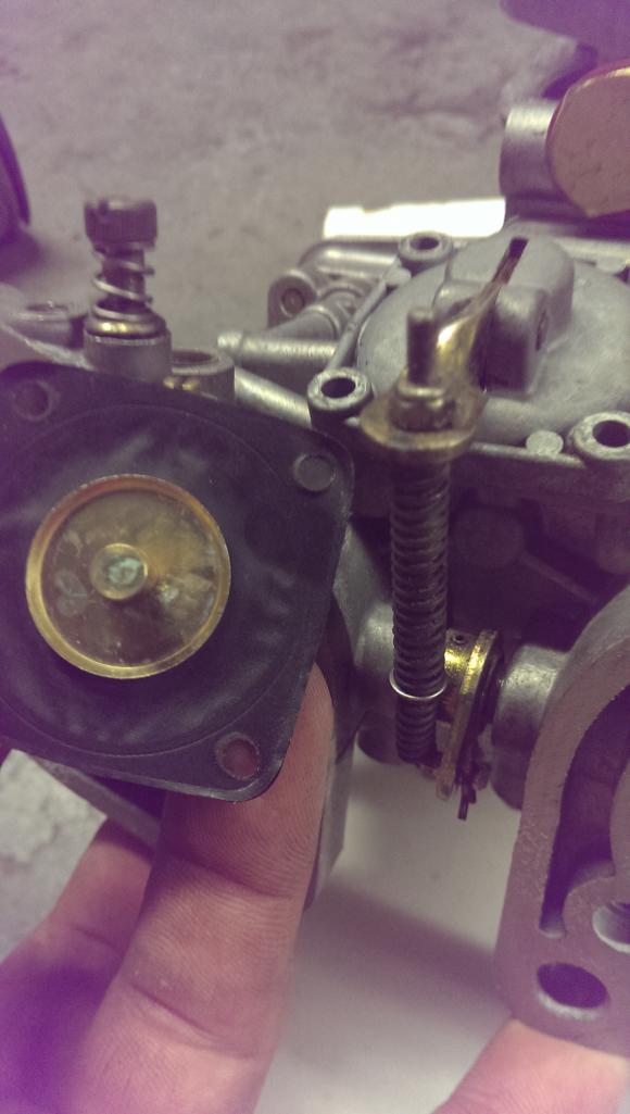 First place the diaphragm on the pump cover. I like to thread the screws through the holes in the diaphragm first to locate it correctly and prevent the rubber from being pinched or the seal leaking upon installation. 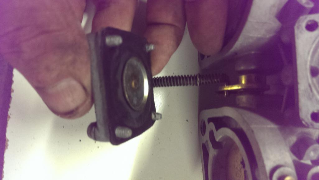 Finally, place the spring on the recess in the body and install the cover. Do not overtighten the screws. Attached thumbnail(s) 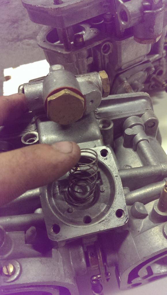
|
|
|
|
| RoadGlue |
Dec 17 2013, 01:21 PM
Post
#24
|
|
Sonoma County Gear Head Group: Admin Posts: 2,033 Joined: 8-January 03 From: Santa Rosa, CA Member No.: 108 Region Association: Northern California |
Great work George! This may be a candidate for the Classics forum.
|
|
|
|
| ThePaintedMan |
Dec 17 2013, 05:05 PM
Post
#25
|
|
Advanced Member Group: Members Posts: 3,886 Joined: 6-September 11 From: St. Petersburg, FL Member No.: 13,527 Region Association: South East States |
Next, move on to the top of the carb. Remove the 19mm brass nut at the fuel line neck, which holds the mesh fuel filter. Clean out the filter and passageway thoroughly and reinstall the filter as well as the new red/orange gasket supplied in the kit. Don't overtighten this fitting, or you'll crush the gasket and ruin it. (Eventually I'd like to find a suitable aluminum style sealing ring to replace the cardboard ones.) You can add a small dab of grease to both sides of this washer to improve the seal and prevent tearing.
If you have not already done so, drive out the float arm pin and remove the float. Be sure to do this with an appropriately sized punch and hammer and with the carb top well supported and far away from a position where it could fall on the ground. If it does, you're likely to ruin the carb top and finding a replacement in good condition is very difficult. I prefer to drive the pin out in the direction outlined below. Sometimes the pin can have a knurled end to it and if that end is forced through the non-slotted end of the float pin tower, it may break. Once the pin is removed, remove the float and needle valve assembly. 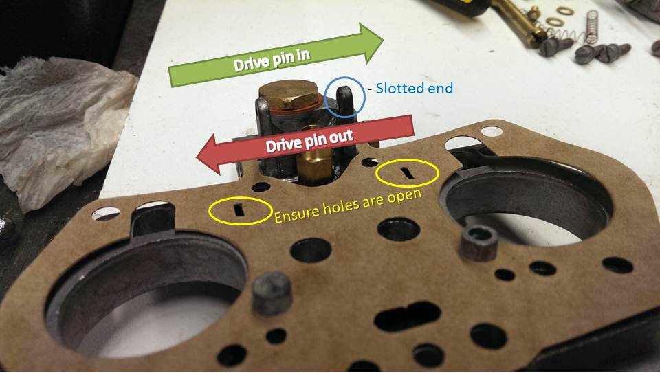 Install the new top gasket (after scraping any residual gasket material off of course) and the needle valve base. Note that there is a small aluminum washer underneath this base that should be replaced with the one in your kit. Also, ensure that the two holes for the idle circuit vents exist on your gasket and will not block the idle circuit vents on the top of the carb bodies. I like to open these holes up a little with a flathead screwdriver just in case. 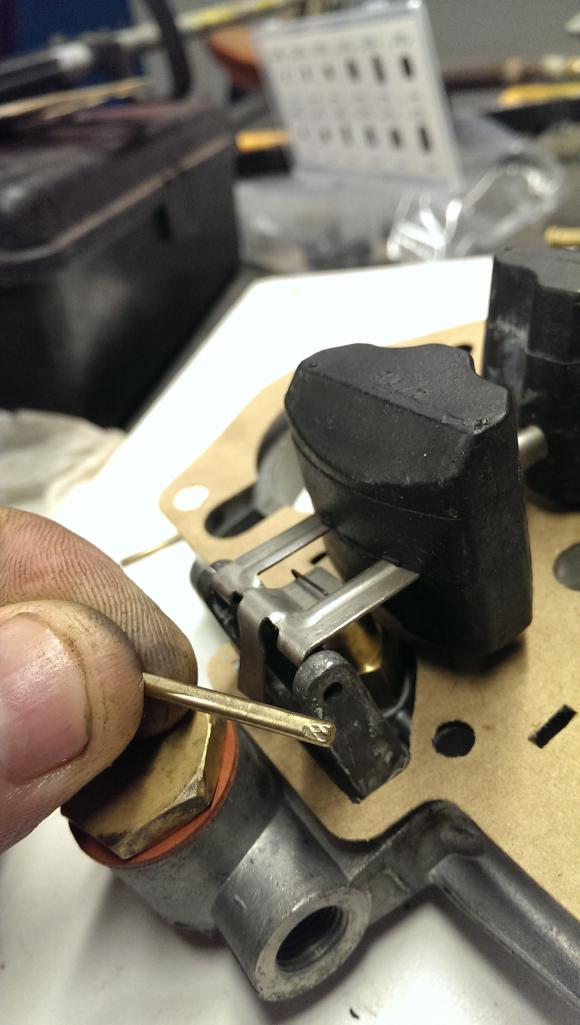 Clean the float of any debris and install the needle valve on the small tab at it's fulcrum. Install both into position and slide the pin back into position. Several taps of the hammer should be able to get it back into position. Again, note the knurled end of the pin and install it so the smooth end goes into the non-slotted holder first. |
|
|
|
| ThePaintedMan |
Dec 17 2013, 05:22 PM
Post
#26
|
|
Advanced Member Group: Members Posts: 3,886 Joined: 6-September 11 From: St. Petersburg, FL Member No.: 13,527 Region Association: South East States |
Now comes the art of setting the float level. Though the methodology is the same, there are varying opinions on what the float level should be on Webers. CB Performance lists a 14 mm gap from the gasket to the very edge of the float, but does not specify a bottom float distance. The Weber Haynes manual and other sources list a 10mm gap and a full-open gap of 32mm, which is what I use. Racers may modify the float level depending on cornering loads and other factors, but the 10/32 measurements work for me.
First, turn the carb top over so that the float is toward the ceiling. Allow the float to rest on the needle valve and do not place any pressure on it. Using a steel ruler or caliper, measure the distance from the gasket to the edge of the float. If it is not 10mm, you will need to bend the small tab that the needle valve is retained on up or down to achieve the proper distance. Don't get frustrated as it may take you several tries to get it right. 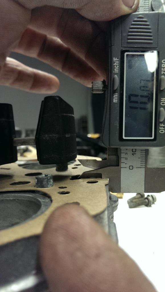 |
|
|
|
| rhodyguy |
Dec 17 2013, 05:25 PM
Post
#27
|
|
Chimp Sanctuary NW. Check it out. Group: Members Posts: 22,080 Joined: 2-March 03 From: Orion's Bell. The BELL! Member No.: 378 Region Association: Galt's Gulch |
nice write up george. don't forget to mention the little o-rings for the idle air mixture screws.
|
|
|
|
| ThePaintedMan |
Dec 17 2013, 05:26 PM
Post
#28
|
|
Advanced Member Group: Members Posts: 3,886 Joined: 6-September 11 From: St. Petersburg, FL Member No.: 13,527 Region Association: South East States |
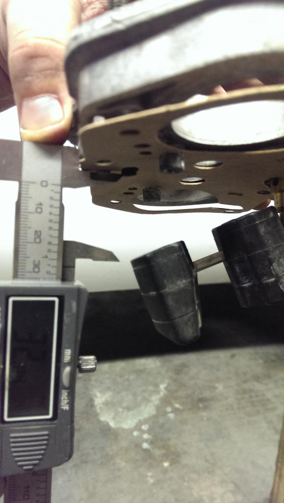
Next, turn the carb top over and allow the float to hang down freely. With the same procedure as before, measure the distance from the gasket to the same edge of the float as in the previous setting. Bend the tab at the back of the float fulcrum point as necessary to achieve the proper distance.
 Once you're happy with the float settings, set the carb top down carefully and move back to the body. Give it one last look through, maybe a shot of carb cleaner in the bowl, and then blow it out upside down with compressed air. This is the last time you'll have to remove debris from it so be thorough. Once complete, install the top on the carb body and tighten down the five screws in a criss-cross pattern. I start with the centermost screw and work across towards the outside of the carb. |
|
|
|
| ThePaintedMan |
Dec 17 2013, 05:42 PM
Post
#29
|
|
Advanced Member Group: Members Posts: 3,886 Joined: 6-September 11 From: St. Petersburg, FL Member No.: 13,527 Region Association: South East States |
Now we need to install the linkage arms and associated hardware. Keep in mind that if you're not rebuilding the carbs that were on your car and you don't know what linkage was used previously, that the arms and spacers that you see may or may not be necessary for your setup. If you have questions, I am familiar with a few different types of linkage, so I might be able to help you determine if you have everything you need, or point you in the right direction of where to order it.
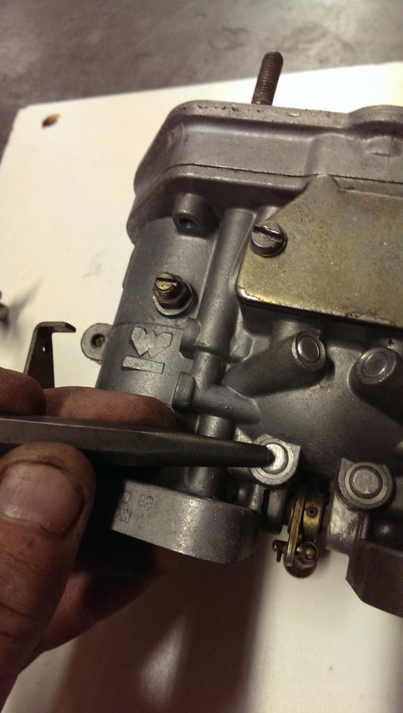
That being said, the general order should look like this. First is the round brass "Cymbal" sealing plate that keeps debris out of the bearing. On early carbs, this was essential since the bearings were not sealed, but they are still present on the later models with sealed bearings. Next is the very, very thin sealing washer seen below. 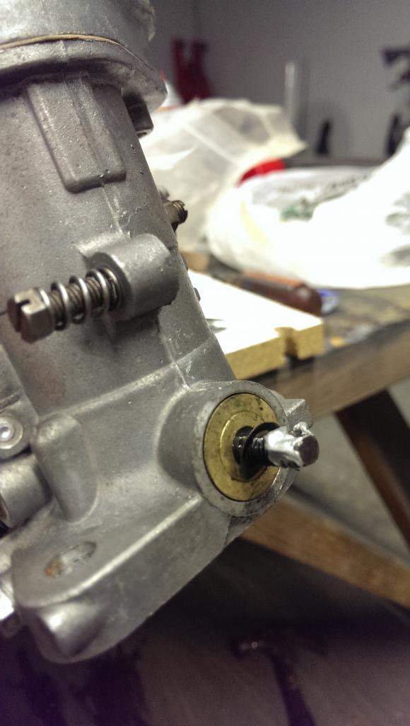 Now add the throttle return spring, if so equipped. There should only be one per carb, and the early Webers did not have them at all. Next is the appropriate throttle linkage arm or spacer, again, depending on which side of the carb you're working on. 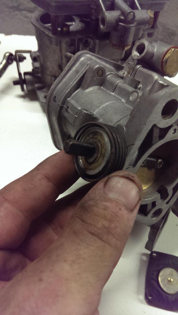 Next install the locking tab washer and 11 mm thin nut. Do NOT forget to put some antiseize on the threads of the throttle shaft. When the nut rusts itself onto the shaft, it is notorious for taking threads with it, which will render the throttle shaft unusable and then you'll have to source a new throttle shaft, not to mention disassembling the entire carb again. 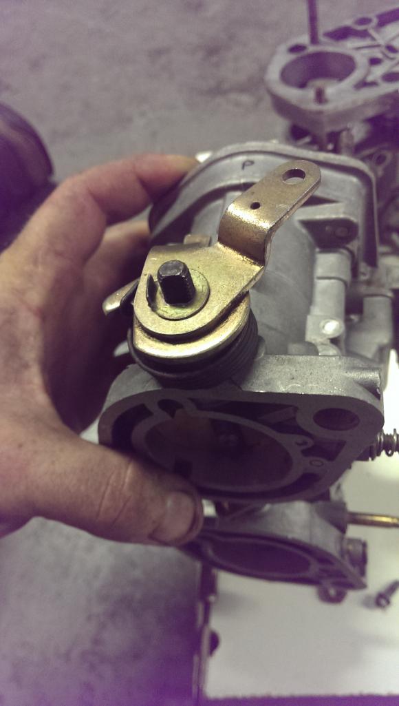 |
|
|
|
| ThePaintedMan |
Dec 17 2013, 05:57 PM
Post
#30
|
|
Advanced Member Group: Members Posts: 3,886 Joined: 6-September 11 From: St. Petersburg, FL Member No.: 13,527 Region Association: South East States |
Just about done. Here is a housekeeping trick that I learned. The casting and drilling/manufacturing process of Webers means that a number of lead plugs are used to seal off several circuits of the carb. Often these plugs will leak or weep even minute amounts of gas over time. While it would be nice to replace all of these lead plugs, I don't feel that it's necessary. Instead, I take the time to use a small punch and peen these plugs in, hopefully mushrooming them out a little bit to prevent leaks. It's much easier to do this while they're out of the car rather than bending over and trying to stop them from leaking after you've got it all together.
 Now is a good time to reassemble the main jet stacks as well. Pretty simple, but each component must be there to serve it's function. Below is a picture of the stack, with main jet, emulsion tube, air correction jet and main jet holder. These are later style main jet holders which "snorkel" above the top of the carb body, in comparison to the lower, early jet holders. Note: if you want to see a cool trick, check out Van Svenson's video on Youtube where he explains how to ensure that the main jets are seating properly. Once they're complete, go ahead and install them. Finally, if you have an earlier style IDF without the adjustable accelerator pump rod, be sure to throw a little grease on the cam and the roller that actuates the accelerator pump rod. Attached thumbnail(s) 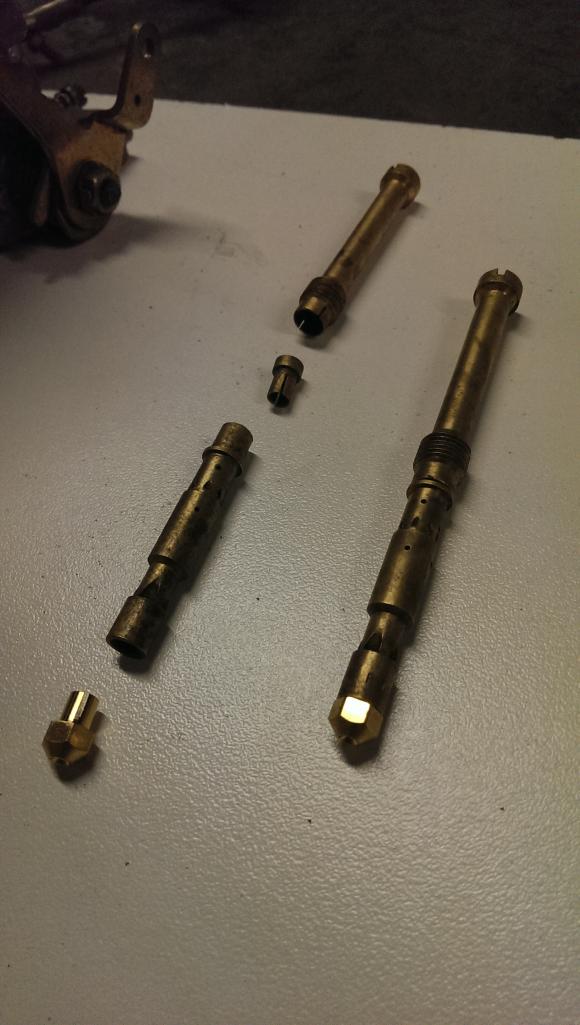
|
|
|
|
| timothy_nd28 |
Dec 17 2013, 06:00 PM
Post
#31
|
|
Advanced Member Group: Members Posts: 2,299 Joined: 25-September 07 From: IN Member No.: 8,154 Region Association: Upper MidWest |
+1 on making this a classic thread
|
|
|
|
| ThePaintedMan |
Dec 17 2013, 06:16 PM
Post
#32
|
|
Advanced Member Group: Members Posts: 3,886 Joined: 6-September 11 From: St. Petersburg, FL Member No.: 13,527 Region Association: South East States |
That just about does it! You should have a nice and clean, fully functioning set of Webers now. I like to hit them with a few light coats of this stuff, CRC 3-36. It works great on protecting aluminum, but it can be difficult to find. You can also use lanolin spray, and either product should ideally be sprayed on the carbs from time to time if possible.
(IMG:http://www.914world.com/bbs2/uploads_offsite/www.restockit.com-13527-1387325759.1.jpg) Here's how Randy's carbs turned out: Attached thumbnail(s) 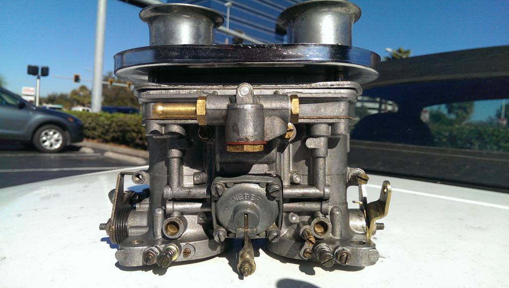
|
|
|
|
| nolift914 |
Dec 17 2013, 06:21 PM
Post
#33
|
|
Autoxer Group: Members Posts: 183 Joined: 24-May 09 From: Rockaway Beach NY Member No.: 10,399 Region Association: None |
QUOTE(ThePaintedMan @ Dec 17 2013, 04:57 PM)  Just about done. Here is a housekeeping trick that I learned. The casting and drilling/manufacturing process of Webers means that a number of lead plugs are used to seal off several circuits of the carb. Often these plugs will leak or weep even minute amounts of gas over time. While it would be nice to replace all of these lead plugs, I don't feel that it's necessary. Instead, I take the time to use a small punch and peen these plugs in, hopefully mushrooming them out a little bit to prevent leaks. It's much easier to do this while they're out of the car rather than bending over and trying to stop them from leaking after you've got it all together. Now is a good time to reassemble the main jet stacks as well. Pretty simple, but each component must be there to serve it's function. Below is a picture of the stack, with main jet, emulsion tube, air correction jet and main jet holder. These are later style main jet holders which "snorkel" above the top of the carb body, in comparison to the lower, early jet holders. Note: if you want to see a cool trick, check out Van Svenson's video on Youtube where he explains how to ensure that the main jets are seating properly. Once they're complete, go ahead and install them. I had one of these plugs completely shoot out during a DE event at Watkins Glenn many years ago, which caused a 1/4" stream of fuel to pour out of the carb across a hot engine. Got Very Lucky that day. Since then I have covered the lead plugs with a two part epoxy. Great write up! (IMG:style_emoticons/default/beerchug.gif) |
|
|
|
| ThePaintedMan |
Dec 17 2013, 09:49 PM
Post
#34
|
|
Advanced Member Group: Members Posts: 3,886 Joined: 6-September 11 From: St. Petersburg, FL Member No.: 13,527 Region Association: South East States |
QUOTE(nolift914 @ Dec 17 2013, 07:21 PM) [I had one of these plugs completely shoot out during a DE event at Watkins Glenn many years ago, which caused a 1/4" stream of fuel to pour out of the carb across a hot engine. Got Very Lucky that day. Since then I have covered the lead plugs with a two part epoxy. Great write up! (IMG:style_emoticons/default/beerchug.gif) That's a great idea! I don't think Randy will have that problem, but it's something I'll definitely consider for my car. Just wanted to thank Randy and McMark for giving me the opportunity to work on his carbs. Mark could have done them, but I needed an excuse to do a writeup. (IMG:style_emoticons/default/smile.gif) Also thanks to Tim, Kevin and everyone else for the kind words and vote of confidence. I know this is pretty much a no-brainer for some folks, but some people are pretty intimidated by carbs and there were some things that I've learned that I wanted to include so others don't have the same headaches I did when I first started rebuilding them. I'd like to do more of these in the future, and eventually a Dellorto writeup. I've got a set of 44s that I'm working on now which will go into the classifieds when I get them done. Going to use some of that money towards a good parts washer and the rest towards Chumpcar endeavors. If there's anything else you guys can think of that I missed, feel free to chime in. |
|
|
|
| nathansnathan |
Dec 28 2013, 08:55 AM
Post
#35
|
|
Senior Member Group: Members Posts: 1,052 Joined: 31-May 10 From: Laguna Beach, CA Member No.: 11,782 Region Association: None |
Nice job. I just read through your thread.
The part about setting the float levels, I have found to be the trickiest. I have heard that unless they are exactly the same side to side they will leak through the needle valves. The critical position is when it closes. I have found it works better to use an allen key between the float and carb top than to use calipers. The other tip which I offer is to blow (with your mouth, yes) through them to make sure they are closed there. Say if they should be closed at 10mm from the top, stick an 11mm allen key between and ensure that they open, 10mm and make sure they close. Another thing to check is to weigh the floats. Dell floats say right on them what they should weigh, but a bad float will weigh a lot more (hard to tell without a scale though). With a heavy float and all else being right, the carb will still drip and fill the cylinders with fuel. |
|
|
|
| rhodyguy |
Dec 28 2013, 09:10 AM
Post
#36
|
|
Chimp Sanctuary NW. Check it out. Group: Members Posts: 22,080 Joined: 2-March 03 From: Orion's Bell. The BELL! Member No.: 378 Region Association: Galt's Gulch |
lost one of those plugs once while driving. engine compartment was covered in fuel. collected what i could out of the car and waited for the car to burst into flames. it didn't. found the plug on the engine shelve, hammered it in with a rock, drove the short distance home, pulled the carbs, made sure the plugs were all fully seated, degrease and epoxyed them. i wasn't driving on a freeway at the time. if i had been i'm sure it would have been a dif story.
|
|
|
|
|
1 User(s) are reading this topic (1 Guests and 0 Anonymous Users)
0 Members:

|
Lo-Fi Version | Time is now: 18th May 2024 - 08:50 PM |
Invision Power Board
v9.1.4 © 2024 IPS, Inc.